What is PLC Programming? Examples, Software, Languages, Work

PLC programming is the backbone of industrial automation. It turns sensors, motors, and machines into coordinated systems that work safely, repeatably, and fast.

Read further to learn what PLC programming is, how programs are organized, how to get started, practical examples in each IEC 61131-3 language, and how major vendor tools (B&R, ABB, Schneider/Modicon, Fatek) fit into your workflow. You’ll also learn how tasks, scan cycles, and subroutines work so you can write clean, reliable code from day one.


What-is-PLC-Programming
Picture of Meshal Alghomiz
Meshal Alghomiz

Meshal Alghomiz is an electrical content writer with a background in Electrical Engineering and affiliation with the Technical and Vocational Training Corporation. He specializes in simplifying complex electrical concepts for technical audiences.

LinkedIn

Key Takeaways:

  • Understand PLC programming fundamentals and why it matters.
  • See real examples in Ladder, FBD, IL/STL, ST, and SFC.
  • Learn how PLC operating modes and scan cycles affect your logic.
  • Get a quick-start toolkit and vendor software overview.

What is PLC Programming?

PLC programming is the process of writing logic that runs on programmable logic controllers to monitor inputs, make decisions, and control outputs. A PLC reads sensors (inputs), processes logic in a deterministic scan cycle, and drives actuators (outputs) such as motors, valves, and solenoids.

PLC programming uses IEC 61131-3 languages: Ladder Diagram (LAD), Function Block Diagram (FBD), Instruction List/Statement List (IL/STL), Structured Text (ST), and Sequential Function Charts (SFC) to define machine behavior.

It makes machines safe, efficient, and consistent. Good PLC code reduces downtime, enforces interlocks, manages alarms, handles faults, and supports diagnostics.

Packaging lines, robotic cells, water treatment, HVAC, process skids, material handling, and energy systems. For example, a bottling line uses PLC logic to coordinate sensors, conveyors, and servos to fill, cap, and label at high speed.

PLC Program Organization

A well-organized PLC program is easier to test, maintain, and scale. Most platforms follow a similar structure:

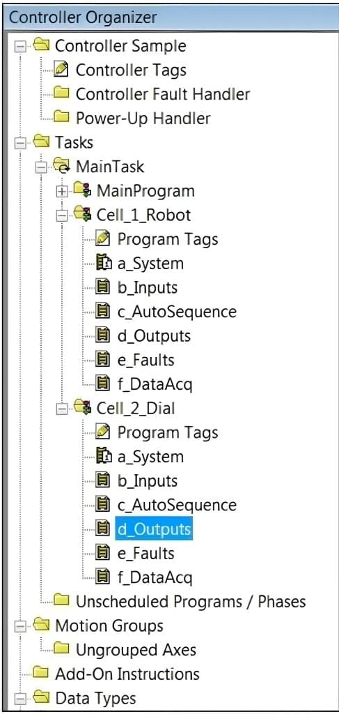
Tasks and programs:

  • Cyclic (periodic) tasks run at a fixed rate (e.g., every 10 ms) for real-time control.
  • Event tasks trigger on specific events (e.g., rising edge of an input).
  • Background tasks run when the CPU is idle (e.g., logging).

Program blocks:

  • Main program (e.g., OB1 in Siemens, Main in Rockwell) coordinates calls to subroutines/function blocks.
  • Function blocks (FBs) encapsulate reusable logic with internal memory (e.g., a motor starter FB).
  • Functions (FCs) return a value without internal memory (e.g., a math routine).

I/O abstraction:

Map physical I/O to internal tags once, then use tags throughout logic. This decouples code from wiring changes.

Naming and standards:

  • Use clear tag names (Motor1_RunCmd, TankLevel_PV).
  • Group by machine area: Safety, Interlocks, Sequences, Motion, Alarms, HMI.

Error handling:

Standard fault handler FBs, alarm buffers, and safe-state logic.

State management:

Use SFC or state machines for complex sequences (Idle → Start → Run → Fault → Recovery).

PLC Program Organization
Figure 1. Example of a Programmable Logic Controller (PLC) program structure. Source: Automation LLC

Tip: Create a library of tested FBs (motors, valves, alarms, ramp/soak, PID wrappers) to speed up new projects and ensure consistency.

Do You Want to Replace or Upgrade your Panel?
True Vision Contracting is the trusted electrical partner for leading firms across Saudi Arabia’s industrial, construction, and infrastructure sectors, offering dependable, compliant, and precise solutions.

How to Start PLC Programming?

You can start with a small demo kit and free vendor software. Follow these steps:

Pick a platform and get software:

Examples: Siemens TIA Portal (trial), Rockwell Studio 5000 (licensed), Codesys (free runtime options), ABB Control Builder, B&R Automation Studio, Schneider EcoStruxure Control Expert, Fatek WinProLadder.

Hardware:

A compact PLC or soft PLC, 24 V DC power supply, a few inputs (pushbuttons, sensors), and outputs (pilot lights, small relays). Many vendors sell starter kits.

Wire and label:

Keep wiring neat. Label terminals and I/O points. Use proper 24 V DC protection.

Create tags and I/O map:

Map inputs (I0.0, %I, etc.) to names like Start_PB, EStop_OK.

Build a simple program:

Start/Stop motor with interlock and fault latch.

Download and test:

Use online mode, force simulated inputs, watch the status bits, and verify behavior.

Add HMI:

Create buttons and indicators for Start, Stop, Fault, and Status.

Document:

Comment code, version-control your project, and keep a change log.

Safety note: Use an E-Stop circuit wired to a safety relay or Safety PLC. Never rely only on software for emergency stops.

What are PLC Programming Examples?

Below are practice solutions for each IEC 61131-3 language. 

The problem: “Start a conveyor with a Start button, stop with a Stop button, prevent start if Guard_Door is open, and latch a Fault if Overload trips. Reset with a Reset button.”

Ladder Logic (LAD)

Start/Stop Seal-in:

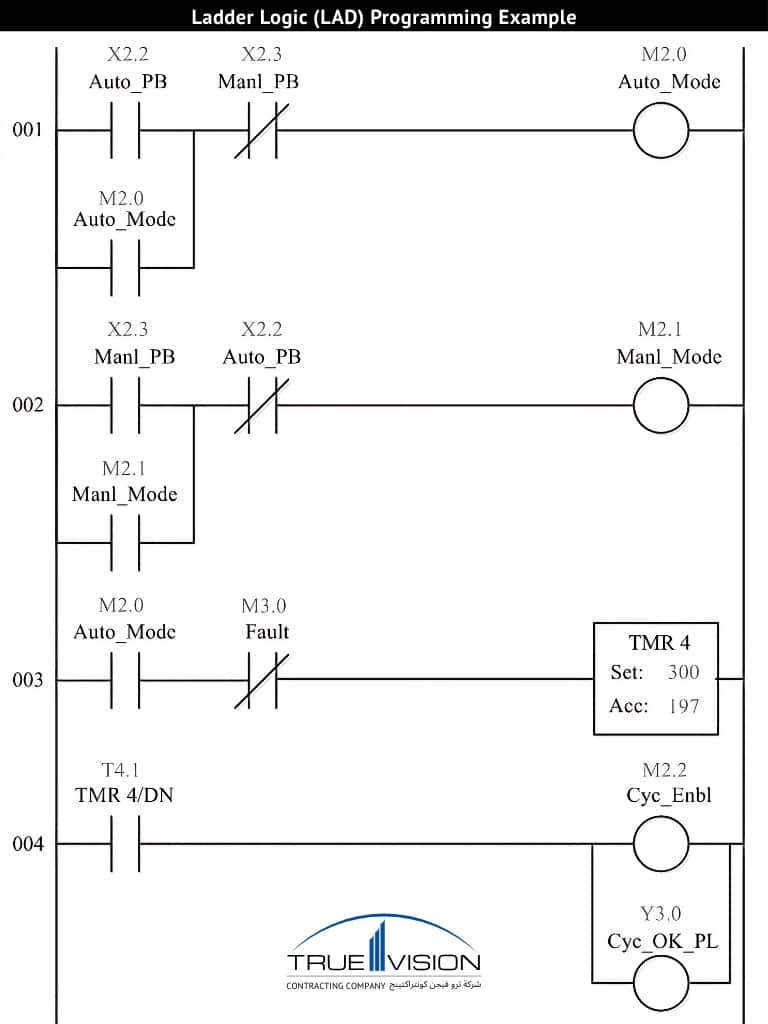
  • Rung 1: Start_PB (NO) in parallel with Motor_Run (seal-in) → AND Stop_PB (NC) → AND Guard_Door_Closed (NO) → Coil: Motor_Run.

Fault latch:

  • Rung 2: Overload (NO) → Coil: Fault_Latched.
  • Rung 3: Reset_PB (NO) → Resets Fault_Latched and Motor_Run.

Interlock:

  • Include EStop_OK and Safe_Ready contacts ahead of the Motor contactor output.
Ladder-Logic-LAD-programming-example-for-PLC-control-systems
Example of Ladder Logic (LAD) PLC programming. Source: Automation LLC

Why it’s useful: Electricians and technicians can read and troubleshoot quickly.

Function Block Diagram (FBD)

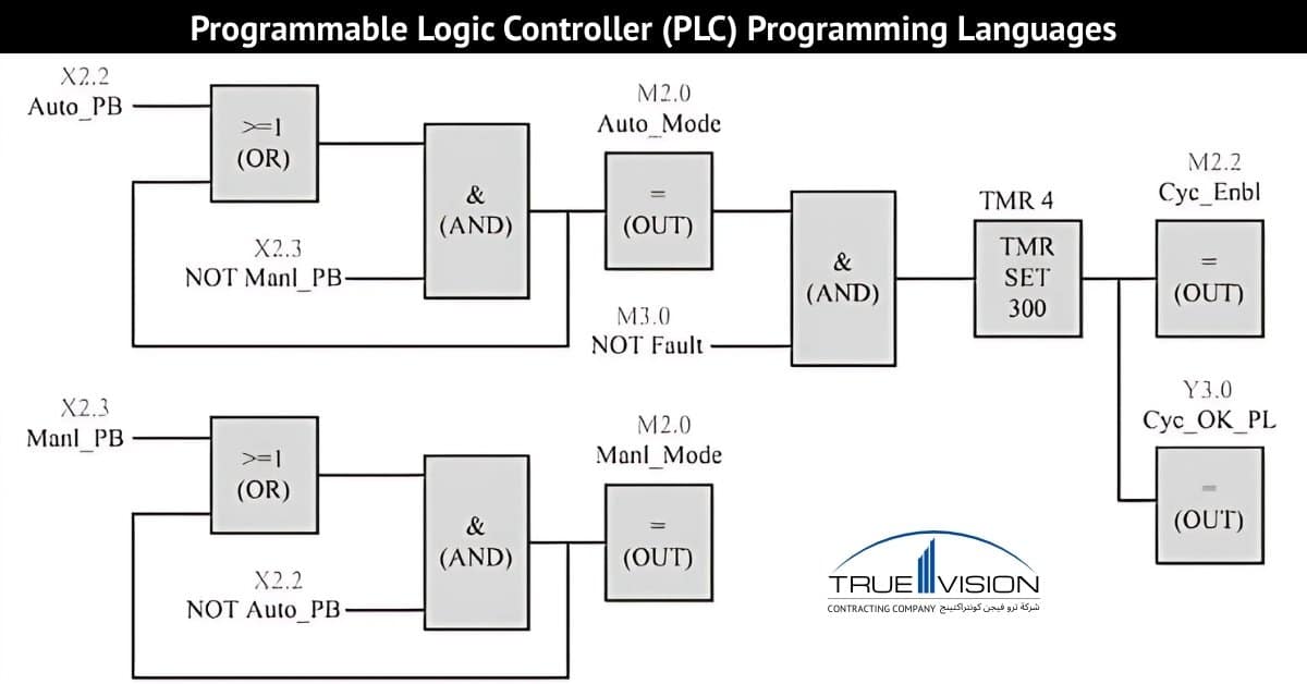
Use SR (Set/Reset) for Motor_Run:

  • Set: Start_PB AND Guard_Door_Closed AND NOT Fault_Latched AND Stop_PB_NC.
  • Reset: Stop_PB OR NOT Guard_Door_Closed OR Fault_Latched.

Fault latch:

  • SR block for Fault_Latched: Set = Overload; Reset = Reset_PB.
Programmable-logic-controller-PLC-programming-languages
Function Block Diagram (FBD) Programming Example

Why it’s useful: Clear signMapplow and easy reuse of standard FBs (timers, counters, PIDs).

Instruction List (IL) / Statement List (STL)

Although deprecated in IEC 61131-3, many legacy systems use it. Conceptual example:

Evaluate start condition:

  • LD Start_PB
  • ANDN Stop_PB
  • AND Guard_Door_Closed
  • ANDN Fault_Latched
  • OR Motor_Run
  • ST Temp_StartSeal

Motor run coil:

  • LD Temp_StartSeal
  • ST Motor_Run

Fault latch:

  • LD Overload
  • OR Fault_Latched
  • ANDN Reset_PB
  • ST Fault_Latched

Why it’s useful: Legacy controllers and memory-efficient logic.

Structured Text (ST)

Readable, powerful, and good for complex logic.

Motor run:

    • StartSeal := (Start_PB AND NOT Stop_PB AND Guard_Door_Closed AND NOT Fault_Latched) OR Motor_Run;
    • IF StartSeal THEN

Motor_Run := TRUE;

END_IF;

IF (Stop_PB OR NOT Guard_Door_Closed OR Fault_Latched) THEN

Motor_Run := FALSE;

END_IF;

Fault latch:

    • IF Overload THEN Fault_Latched := TRUE; END_IF;
    • IF Reset_PB THEN Fault_Latched := FALSE; END_IF;

Why it’s useful: Compact code, easy math/arrays/recipes, resembles high-level languages.

Sequential Function Charts (SFC)

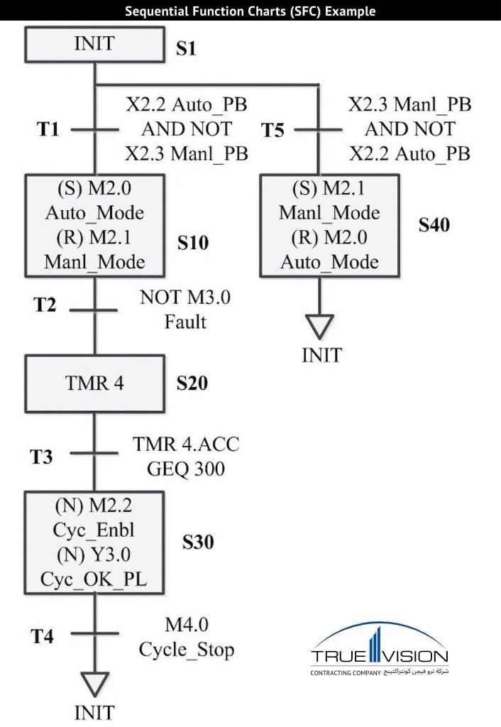
Model the machine as states with transitions:

    • Steps: Idle → StartSeq → Running → Fault → Recovery.

Transitions:

      • Idle → StartSeq: Start_PB AND Guard_Door_Closed AND NOT Fault_Latched.
      • StartSeq → Running: Motor feedback OK.
      • Running → Fault: Overload OR NOT Guard_Door_Closed.
      • Fault → Recovery: Reset_PB AND Fault cleared.
      • Recovery → Idle: All safe; motor stopped.

Actions:

    • Running step sets Motor_Run.
    • Fault step sets the Alarm.
PLC-Sequential-Function-Charts-SFC-programming-example-with-steps-and-transitions
Example of Sequential Function Chart (SFC) PLC programming. Source: Automation LLC

Why it’s useful: Clear sequencing and interlocks for complex machines.

What is PLC Operational Modes?

Most PLCs support 3 operational modes:

  • RUN: The PLC scans inputs, executes logic, and updates outputs cyclically. Use RUN for normal production.
  • STOP: The PLC halts logic execution. Outputs may de-energize or hold last state, depending on platform and configuration. Use STOP for maintenance.
  • PROGRAM (or Remote/Monitor): Allows online edits, downloads, and debugging while controlling how outputs behave during changes. Many platforms support online edits in RUN with restrictions.

Best practice: Define safe states on STOP, and use controlled transitions with bypass logic only where risk-assessed.

What are PLC STL Programming Examples?

Statement List (STL) programming in PLCs is an assembly-like language often used for compact and deterministic instruction control. A common example is an edge-detected counter that increments when a sensor toggles from 0 to 1. For rising edge detection, the logic involves loading the sensor state (LD Sensor), performing an XOR operation with the previous state (XOR Sensor_Last), and storing the result as RisingEdge. The sensor state is then updated (ST Sensor_Last).

To count on the rising edge, the program checks the RisingEdge condition, ensures no faults are latched (ANDN Fault_Latched), and enables increment (= EN_Inc). The counter value is then incremented (ADD Cnt 1) and stored (ST Cnt). STL programming is particularly useful for legacy Siemens S7 controllers or older systems where precise, deterministic control is required.

What is B&R PLC Programming?

B&R Automation Studio is a comprehensive engineering environment designed for PLCs, motion control, safety, and HMI development. It supports IEC 61131-3 programming languages, including Ladder Diagram (LAD), Function Block Diagram (FBD), Structured Text (ST), and Sequential Function Chart (SFC).

The platform features mapp Technology, which provides prebuilt modules for alarms, motion, temperature control, and recipes, significantly accelerating development. With integrated simulation and trace tools, users can easily perform tuning and diagnostics. 

Additionally, Automation Studio supports various fieldbus protocols such as POWERLINK, OPC UA, and Ethernet-based networks. The workflow involves creating a project, adding targets like X20 or ACOPOS, configuring I/O and tasks, writing logic, building, simulating, and deploying the application. Its strong motion integration and modular software design make it ideal for developing high-performance machines.

What is the Fatek PLC Programming Manual?

Fatek’s WinProLadder is a free, Windows-based programming environment designed specifically for Ladder programming on Fatek PLCs. It offers a ladder-centric interface with features like timers, counters, math functions, and high-speed I/O capabilities. The platform includes a built-in device monitor, force tools, and supports online edits, making it user-friendly and efficient. 

With simple addressing and comment-friendly tag descriptions, it streamlines the programming process. To use WinProLadder, users can create a new project, select the PLC model, define I/O, write ladder rungs (such as a motor starter), download the program, and monitor its status in real time. This tool is particularly beneficial for students, small machines, and cost-sensitive projects due to its low barrier to entry and ease of use.

How to Use ABB PLC Programming Software?

ABB Control Builder (often paired with AC500/Automation Builder) covers PLC, safety, drives, and visualization.

Capabilities:

  • IEC 61131-3 languages, including ST for advanced logic.
  • Task configuration, online monitoring, and diagnostics.
  • Libraries for motion, PID, communication, and safety.

Getting started:

  • Install Automation Builder, add AC500 CPU and I/O modules, configure Ethernet/fieldbuses, program logic, compile, download, and test.

How to Use Schneider PLC Programming Software?

EcoStruxure Control Expert (formerly Unity Pro) is Schneider’s engineering suite for Modicon platforms.

Highlights:

  • Supports IEC 61131-3 languages (LD, FBD, ST, SFC, IL for legacy).
  • DFBs (Derived Function Blocks) for custom reusable blocks.
  • Integrated simulation, variable monitoring, and diagnostics.

Steps:

  • New project → choose PLC (M340/M580/Quantum) → configure racks/modules → write logic → simulate → download → commission.

Strength:

  • Strong ecosystem with Modicon PLCs, flexible libraries, and good lifecycle tooling.

What is Modicon Quantum PLC Programming Software?

The Modicon Quantum platform, though considered a legacy system, remains widely used in process industries due to its reliability and stability. Historically programmed with Unity Pro, now known as EcoStruxure Control Expert, it is well-suited for applications requiring large I/O counts, distributed architectures, and long-life platforms in process plants. 

Key features include redundancy options, robust networking capabilities such as Modbus and Ethernet, and strong diagnostic tools for efficient troubleshooting. However, many plants are now planning migrations to the newer Modicon M580 platform, with EcoStruxure Control Expert simplifying the conversion process and ensuring a smoother transition to modern systems.

What are the PLC Programming Languages (IEC 61131-3)?

The 5 PLC Programming Languages (IEC 61131-3) standard languages are:

  • Ladder Diagram (LAD): Relay-style graphics. Best for discrete logic, easy troubleshooting.
  • Function Block Diagram (FBD): Blocks and signals. Great for analog, PID, and reusable logic.
  • Instruction List (IL)/Statement List (STL): Textual, assembly-like. Deprecated in the standard but exists in legacy systems.
  • Structured Text (ST): High-level, Pascal-like. Ideal for math, arrays, strings, and complex algorithms.
  • Sequential Function Charts (SFC): Steps and transitions. Best for sequences and state machines.

Tip: Most projects mix languages; LAD for interlocks, FBD for PIDs, ST for logic-heavy routines, SFC for sequences.

How PLC Programming Languages Work?

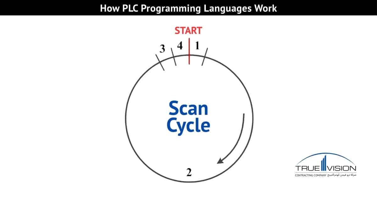
PLC Programming languages work depends on tasks and the PLC scan model:

Scan cycle:

  • Read inputs → Execute logic → Update outputs → Housekeeping. Repeat each task at its period.

Task types:

  • Fast control tasks (e.g., 5–10 ms) for motion/interlocks.
  • Slower tasks (e.g., 100–500 ms) for logging or noncritical checks.

Language interaction:

  • You can call an ST function from a Ladder routine or use an FBD PID inside an SFC step.

Determinism and timing:

  • Keep CPU load below target (e.g., <70%). Use execution time profiling and optimize heavy routines.

Edge detection and races:

  • Use rising/falling edge coils or standard edge FBs to avoid double triggers.

Data handling:

  • Use typed variables, UDTs/structures, and arrays for clean data models. Map I/O once; pass logical tags to FBs.
How-PLC-programming-languages-work
A PLC scan cycle: reading physical inputs, executing logic sequentially, updating the output image table, and performing system checks and housekeeping tasks. Source: Automation LLC

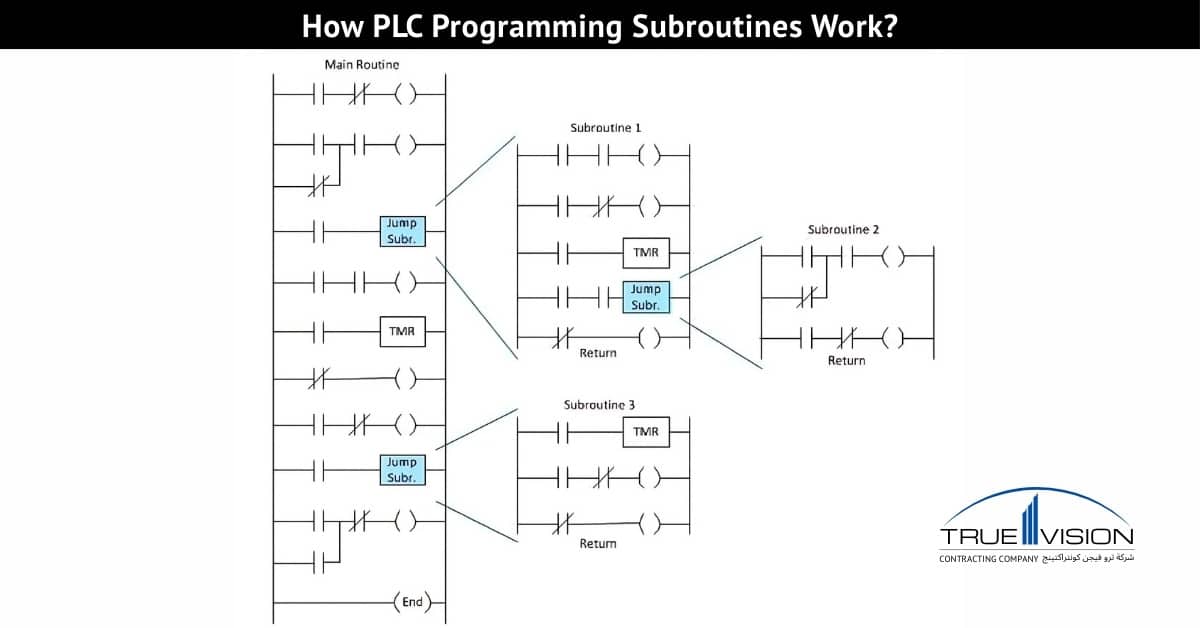
How PLC Programming Subroutines Work?

PLC Programming Subroutines and function blocks help you write modular, reusable code:

Functions (FCs):

  • No internal memory; return a value. Use for calculations (e.g., filter, scaling).

Function Blocks (FBs):

  • Have instance memory; ideal for devices that need state (e.g., a valve with open/close timers and fault history).

Derived Function Blocks (DFBs):

  • Custom composite blocks that wrap multiple behaviors into one standardized unit.

Reuse pattern:

  • Create a Motor_Starter FB with inputs (Start, Stop, Permissive), outputs (RunCmd, Fault), and parameters (StartDelay). Instantiate for Motor1, Motor2, etc.

Interfaces:

  • Keep IN/OUT parameters consistent. Use UDTs for device status to standardize HMI bindings.

Testing:

  • Unit test FBs offline or with simulation. Add status bits like InitOK, FaultCode for easier debugging.
How-PLC-Programming-Subroutines-Work
PLC scanning starts with the first rung of the main routine; every PLC includes this designated routine. A subroutine is executed when the scan encounters a jump or call. Source: Automation LLC

Conclusion

Start PLC programming by downloading a vendor-specific environment like Codesys, TIA Portal (trial), EcoStruxure Control Expert, Automation Builder, B&R Automation Studio, or Fatek WinProLadder. Build a Start/Stop/Interlock example in Ladder Diagram (LAD) and Structured Text (ST), adding an alarm latch and HMI indicators.

Create a reusable function block (FB), such as Motor_Starter, and deploy it across two motors. Measure task load, optimize scan time by moving noncritical logic to slower tasks, and document your project with comments, a change log, and version control. These steps ensure clean, scalable PLC programs for any application.

TVC Panels Products

Do You Want Free Estimate!
True Vision Contracting is the trusted electrical partner for leading firms across Saudi Arabia’s industrial, construction, and infrastructure sectors, offering dependable, compliant, and precise solutions.